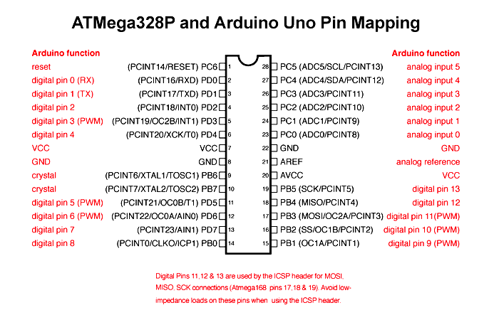


When using the digital pins for API functions that include pinMode(), digitalWrite(), digitalRead(), analogWrite(), as well as others, you will use digital pin numbers like 0, 1, 2, that match the digital pin numbers printed on the PCB.įor analogWrite() the only digital pins that work are the ones with the ~ next to them.

So while all this sounds messy (and it is) the mess is for the most a bit hidden if you use some of the symbols available and keep a few things in mind.
#MATCHING ARDUINO UNO PINOUT TO NANO PINOUT CODE#
(remember analog pin 0 is not the same pin as digital pin 0)īut if you use a constant that is bigger than the maximum analog channels, the code will assume you passed in an Arduino digital pin number will attempt to convert it back to the matching Arduino analog pin number.įor example on the UNO if you use 14 in analogWrite() it will use Arduino analog pin 0. that you meant Arduino analog pin and not Arduino digital pin. There is some ugly code in the core code that assumes that if you give a naked constant to AnalogRead() like 0, 1, etc. Note that on the official Arduino boards you will see a tilda ~ next to the digital pins that support pwm which means that they support the digital function analogWrite() So when using digital API functions like digitalWrite(), pinMode(), digitalRead(), analogWrite() you use an Arduino digital pin number, and for an analog function like analogWrite() you use an Arduino analog pin number. Things get messy when using the analog APIs, since the pin numbering space for analog pins is different than the digital pins.Ĭompounding to the confusion is that analogWrite() has nothing to do with analog as it is performing a digital operation and uses Arduino digital pin numbers whereas analogRead() is an analog function and uses Arduino analog pin numbers.Īrduino analog pin 0 is not the same as Arduino digital pin 0 for digital API functions you use an Arduino digital pin number so if you see a 4 on the PCB then you use 4, if you see 13 you use 13. In order to get the desired pin labeled on the board you must use the proper arduino pin number. The Arduino core code uses mapping tables to map the Arduino pin numbers to a particular port and bit number which correspond to a particular phsysical pin number. You never use AVR chip physical pin numbers.Īll the Arduno API functions use Arduino pin numbers. If that's the case, for analog pins would I do the same thing. But of course, I haven't touched this stuff in a year or more so I could be perfectly wrong. I don't remember it being D2 is #2, D3 is #3, D4 is #4, etc. So, can someone clear this one up for me? As I remember it, what you usually did was use the board pin number to address the output pins, or if you were using a standalone atmega, you addressed with the chip pin number. Changed that in the sketch, and now the circuit is up and running. Playing around with the pins and blink sketch, I found that D2 is #2, D3 is #3, D4 is #4, and so on. LEDs don't work, shifters don't work, nothing works. So I set up my sketch: #define DIG2 5Īnd so on. According to what I see on the internet, D2 is board pin 5, D3 board pin 6, and so on. I plug the nano into the protoboard, and look up a board pinout. I pull up the sketch on an UNO, plug in my circuit, and it works just fine. The ones that use the CH340 USB that's a pain to get going. So I bought one of those cheap $2 chinese nano clones off Ebay. So I decided to take it a step further and use a nano with a home made shield to neaten it up and shrink the board. Then I modified it to run directly from a homemade board with an ATMEGA328 on it. I had a project involving LEDs and shift registers that I did some time ago using an UNO. Hopefully someone will help me get to the bottom of this one. So, I'm not sure if I remember wrong, if something changed with the functions, or if it's just me and my cheapo parts :grin: It's been quite a while since I wrote my last Arduino sketch, probably around a year or more.


 0 kommentar(er)
